How did you end up reconstructing the subframe?
I remember partly what you n your dad were going to do, interested to see how it comes out.
arklan f8c engine swap
No offence but your going to have a hard time engineering this thing if the engineer has a look at this build thread. Like Brayden said, the car will not handle, the geometry is all out. Also very dangerous on the road, for you and other vehicles. I do admire you tackled it yourself though.
╔═══╗ ♪
║███║ ♫
║ (●) ║ ♫
╚═══╝
║███║ ♫
║ (●) ║ ♫
╚═══╝

Arklan PM'd me to say that he's rebuilt the frame in a different position. I'll wait to see pics before I pass final judgement, but it would need to be quite well fabricated to control the flex in the lower control arm inner mounts created by lopping off the original frame.
F8B EFI turbo - Three pots and a snail.
if u look in some of the pics u can actually see it, on the engine side its painted black and on the gearbox side it hasnt been painted so its silver.
i didnt want to post pics until we go to weld it coz i cant get good pics while the engine is sitting on it.
its made out of 25/50 box tube with flat bar welded to the top.
i didnt want to post pics until we go to weld it coz i cant get good pics while the engine is sitting on it.
its made out of 25/50 box tube with flat bar welded to the top.
ok got it done today, dad welded the pieces on. today was the only day in a few weeks that we have both had off work.
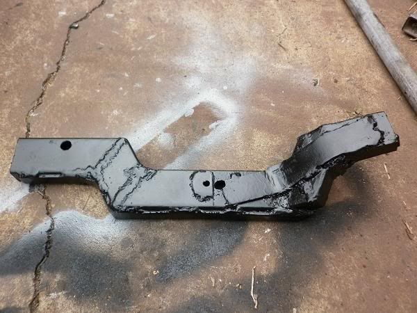
^ for the engine side
^ for the gearbox side
waiting for the paint to dry.
the brackets r made of 25/50 box tube with 3mm flat bar reinforcement.
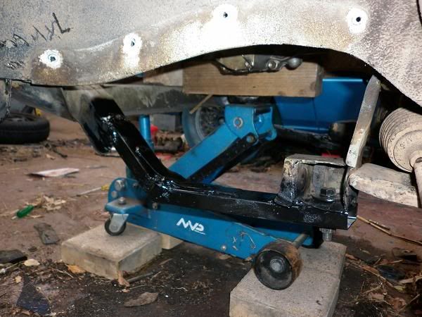
the only way to make the engine fit without doing any cosmetic changes was to reshape the subframe making it wider so the sump can go inside. (using the mboy engine mount bracket)
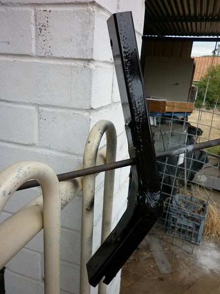
on the engine side the subframe was made wider to fit the sump while on the gearbox side the subframe was made lower so the engine would be level.
^ engine side
^ gearbox side
once cleaned and painted theyv come up really neat, once its on the road and gets a bit of mud and usual wear and tear it will look like it was there for years
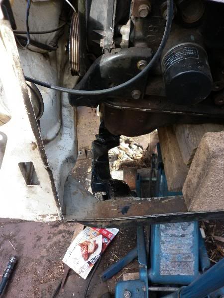
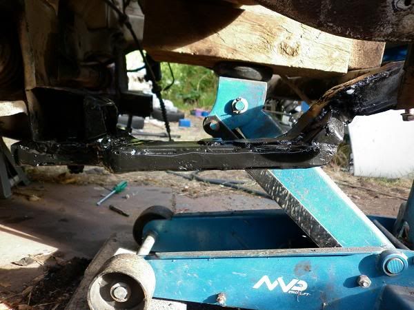
^ so you can see how much wider the bracket is for the engine to sit in.
there are high tensile bolts sitting in the wishbone holder things to hold the bracket up while at the front the brackets sleeve inside where the old pieces were cut off. even if every single weld in the whole thing breaks off it still wont go anywhere because of the bolt, it is very strong.
before welding everything in, we hooked the whole lot up, sway bar, drive shafts, struts, tie rods and even the tyres to make sure the engine was perfect.
^ for the engine side
^ for the gearbox side
waiting for the paint to dry.
the brackets r made of 25/50 box tube with 3mm flat bar reinforcement.
the only way to make the engine fit without doing any cosmetic changes was to reshape the subframe making it wider so the sump can go inside. (using the mboy engine mount bracket)
on the engine side the subframe was made wider to fit the sump while on the gearbox side the subframe was made lower so the engine would be level.
^ engine side
^ gearbox side
once cleaned and painted theyv come up really neat, once its on the road and gets a bit of mud and usual wear and tear it will look like it was there for years
^ so you can see how much wider the bracket is for the engine to sit in.
there are high tensile bolts sitting in the wishbone holder things to hold the bracket up while at the front the brackets sleeve inside where the old pieces were cut off. even if every single weld in the whole thing breaks off it still wont go anywhere because of the bolt, it is very strong.
before welding everything in, we hooked the whole lot up, sway bar, drive shafts, struts, tie rods and even the tyres to make sure the engine was perfect.
Welding or modifications to subframes or suspension components/differentials is not aloud. In saying that my daily has a locked diff. seems like you have done alot of work, maybe use that as a template. It wont pass engineers cert. Unless your not planning on having it engineered?
╔═══╗ ♪
║███║ ♫
║ (●) ║ ♫
╚═══╝
║███║ ♫
║ (●) ║ ♫
╚═══╝
Wow... just wow.  After staring at these pictures for a few minutes I don't even know where to start.
F8B EFI turbo - Three pots and a snail.
^ lol x2
http://www.calaisturbo.com.au/showthread.php?t=180305
Mate somethings you just have to pay to get done or be lucky enough to know someone with the skills to do the job required. There is no shame in admitting that you may lack the experience and skillset needed at this particular time, but please don't put that vehicle on the road without it first being engineered. Things can go wrong with vehicles at the best of times let alone with ones that may have been modified incorrectly. Mate, not having ago or trying to lecture you (I could possibly do no better), but you need to know your limitations. Stay safe
Pete
Pete
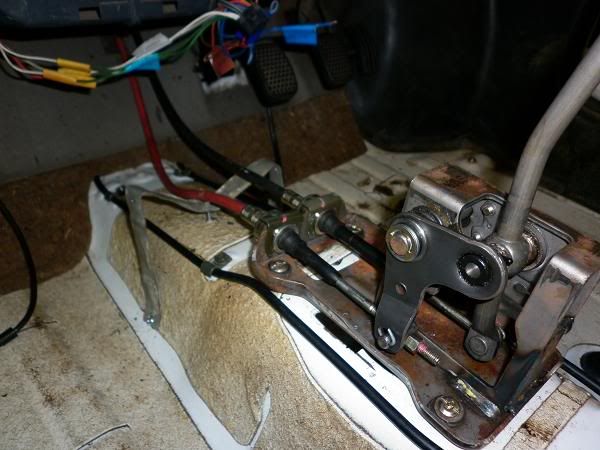
this is how i put in the centre console and gearstick.
the birds nest of wiring from the radio can be clearly seen
the back of the console i have a piece of flatbar shaped like an M it bolts on to the hump and to the original holes of the console and then theres an adjustment bolt in the middle to give it strength and adjust tightness.
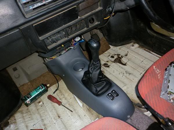
the console ill leave out until my cousins bf has finished all the electrical work
already have electric windows but i put switches from an accord in the doors, the ones in the console are just there for show unless i find some fun gadget to hook them in to.
as for the engine, the car is sitting on the ground on its own wheels it just needs the exhaust and fuel lines done and its good to go for my cousins bf to do the electrical
as for the engine, the car is sitting on the ground on its own wheels it just needs the exhaust and fuel lines done and its good to go for my cousins bf to do the electrical
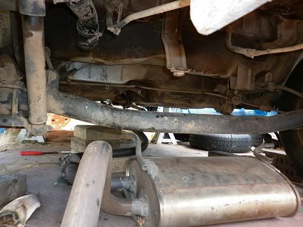
this is the matiz exhaust pipe that iv stuck under the boy to see if it would fit or not, surprisingly it does! almost
the problem here is the muffler and ascosiated pipes going on the fuel tank side with all the pipes for the tank, so..
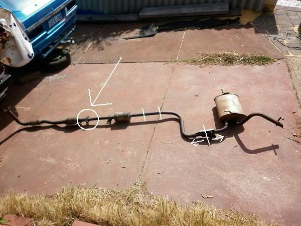
theres a 2 bolt joiner in the middle (circled) so i just flip it over and its good to go (almost)
once i put it up again, the axle is in the way so the pipes will have to be played with to make it fit and also to make it clear the tank. the muffler will go in the spot of the spare wheel.
ill put up pics when i get it in place.
a comparison of the 2 exhaust pipes, the matiz one needs to be bent a little bit to fit around the tank and the muffler is sitting where the back axle is sposed to be so when the pipe is bent up to fit the tank, it should push the muffler forward enough to clear the axle (fingers crossed)
http://www.teammightyboy.com/forum/view ... f=1&t=6445
link to a thread in mighty boy about fuel tanks, just to keep all the information in one place
http://www.teammightyboy.com/forum/view ... f=1&t=6445
link to a thread in mighty boy about fuel tanks, just to keep all the information in one place
- Attachments
-
-