Motorbike engine conversion
If you have a MightyBoy and a need for speed, this bike engine conversion might be just what you're looking for.
This was quite a large undertaking that combined all my skills as an Electrical Engineer, Mechanical Engineer and an Automotive Engineer into one project. This project underlined how I can combine all my design and fabrication skills into one prototype to perform the way it was intended to with no iterations.
The initial concept came from a passion of racing and driving fast. Instead of spending $30,000 on a supercharged V8 to have a fast car, I decided to scale down and utilise a high power to weight combination that would achieve the same results.
The objective here was to build a fast car for $3,500 to show a culmination of all my skills put together and then to make a profit at the end of it once it was sold.
I achieved all of these objectives. I came under budget at $3,300, drove the car for a year to test the reliability of it, then sold the car for $6,500. The motorbike engine conversion kit for that car then was sold for $4,000. An accurate log of all the expenses and fabrication time spent on each component was kept. Total fabrication time came close to 350 hours over 4 months.

Motorbike engine conversion - Honda CBR1100
By James Hawkins
Sourcing an engine and ute
The first thing in starting out this project was picking a high-powered motorcycle engine. The Hayabusa 1300cc was first preference at 180hp, but finding a crashed one at auction cheap was hard to accomplish in Australia, as they sell smashed for around $4,000 dollars.
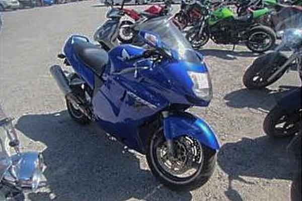
A 2001 Honda CBR 1100cc came up at auction, which has only 15hp less. Because it’s not as popular, it sold for only $850 dollars. This was a great buy, as it wasn’t too damaged, and the tires, wheels, fairing, seat, and suspension were sold for a $1,000 dollars. This paid off the outlaid expense in purchasing the bike for the engine.
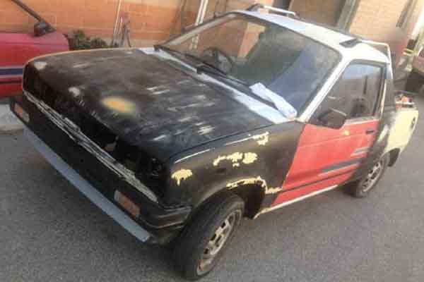
From there I sourced a Suzuki MightyBoy from the online market and came across one for $550. It was half way through being restored and had been sitting in a shed for the past seven years. It had no rust in it, which is really rare to find in a1985 model one of these.
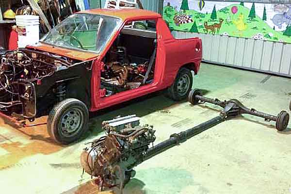
Both the bike and car were transported to my Dad’s shed, where I stripped the bike to get the engine out of and the car to get ready for paint.
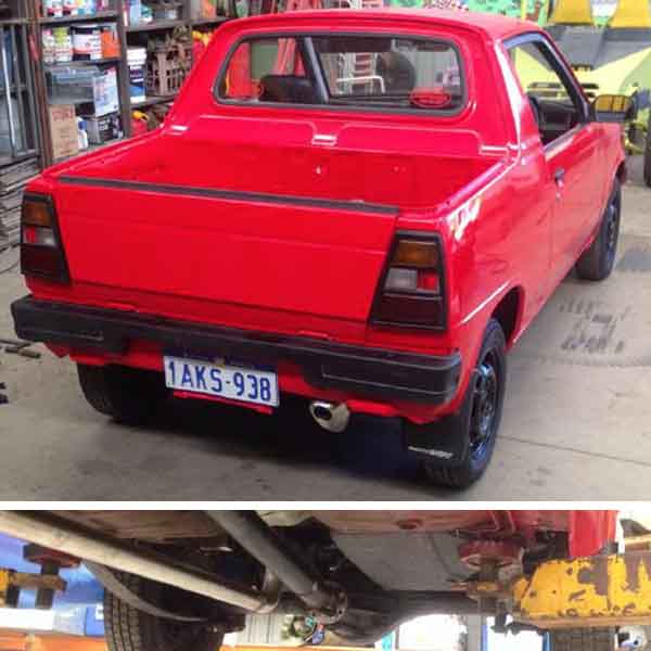
The ute was primed and painted 'Sting Red'.
Design theory
It was decided to put the engine in the front. A lot of motorbike engine conversions on YouTube have the bike engine installed in the back of the car. This is really messy and cuts a lot of corners.
It affects the handling of the car when trying to turn, as there is no weight in the front any more. They also run a chain and solid axle on the rear, to drive the car as well. This creates extra noise from the chain, which also creates more maintenance on the vehicle, from needing to lubricate the chain every time you drive it. The chain also then has to be adjusted and the engine solid mounted to keep the sprockets aligned. This further increases vibration noise in the car and was undesirable.
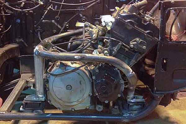
I knew I could do much better than that, so I mounted the motor in the front of the car on rubber engine mounts, and used a driveshaft to provide power to the rear tires of the vehicle through a differential. This eliminated maintenance of the driveline and made the car handle well from the evenly distributed weight. It also kept the car quiet inside from isolating the engine from the chassis with the rubber mounts.The bike engine was test fitted to see roughly how it would sit in the car. It was a tight fit but I made it work.
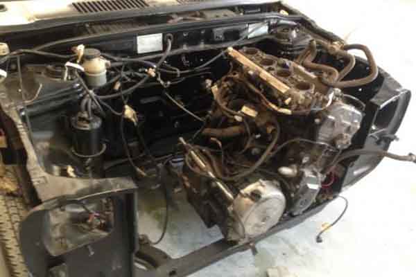
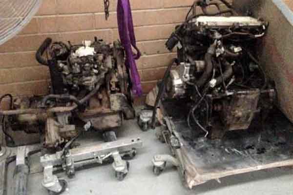
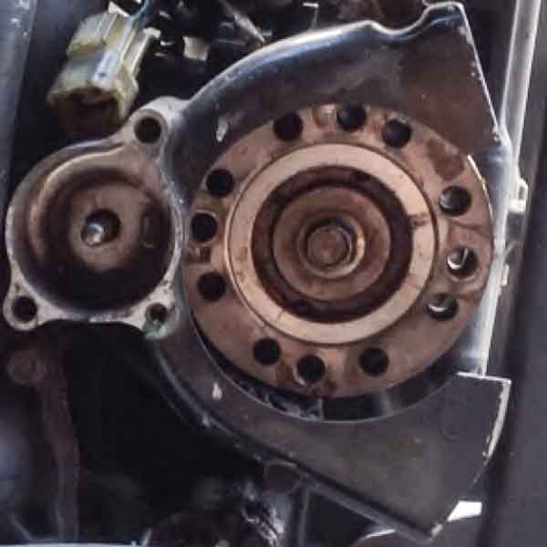
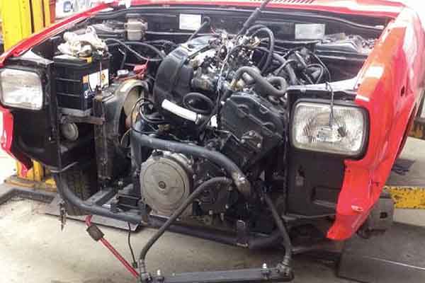
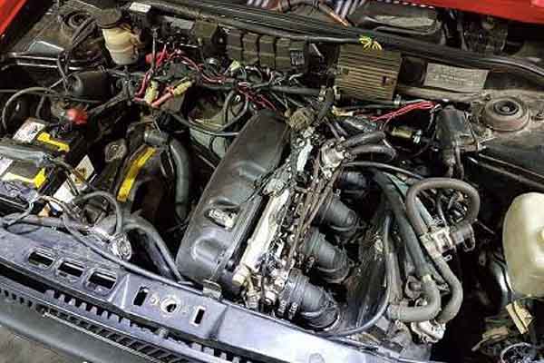
The engine had to be slid all the way to the left of the engine compartment so the output sprocket would line up with the middle of the car where the tail shaft would run through. Having the engine to the left also counterbalanced and offset the driver’s weight (In Australia, the driver is on the right side of the vehicle). A comparison of the old engine on the left, versus the motorbike engine on the right, as shown.
Setting up the driveline
Coming up with a suitable combination of differential, tailshaft and coupling required measurements, maths and lot of research.
Motorbikes and cars both have different size tyres and final drive gear ratios. Before selecting a differential for the car, the correct differential ratio had to be calculated. This was based off many inputs.
One input was that the motorbike could do 75mph in first gear at redline, and had a top speed of 180 mph. These speeds were unnecessary for the project, and greater acceleration advantages could be gained by changing the gear ratio to 60% of that. This would multiply the torque of the engine further, to compensate for the extra weight of the car.
The number 60% came from the speed I wanted to achieve out of first gear whilst also maintaining a relatively low RPM at highway speeds. Gearing the car down to 60%, gave a first gear top speed of 46 mph. Gearing down any further would make the highway speed RPM too high in last gear.
Working out the differential ratio to achieve a 60% gear reduction ratio was calculated by comparing the car and bike tire circumference ratios, and factoring in the sprocket ratios from the bike as well. A final differential ratio to accomplish 60% of the speed of the bike, whilst accommodating the 12-inch tires on the car, was calculated to be 3.5:1.
Differential
Deciding what type of differential to install was the hardest decision to make as there were many parameters to optimise. In order to fit a differential into this front wheel drive car, many factors had to be taken into account including differential ratio, stud pattern, mounting points, LSD compatibility, cost, weight, width, brake type and size, handbrake cable and brake line fitting types. The more of these variables that matched what’s suited to the car, the less modifications needed to be made to the differential and the cheaper it is. There were several aspects that made this choice difficult.
1. Specifications: Trying to find a low enough differential ratio of 3.5:1 (that also came from a small vehicle to match the width and keep the weight down) was near impossible to find, especially with an LSD centre. Most small vehicles had a ratio of around 4:1 to 6:1 and were open centre.
2. Wheel size: Having a 12” rim size meant no disc brake type differential would fit inside these small wheels. The differential had to use drum brakes with drums no bigger than seven inches in diameter. This proved scarce to find as well, since most small car differentials had drum brake sizes of eight inches an up to fit 13” wheels and larger.
3. Suspension: Another aspect was choosing between an independent type or leaf spring type differential. With a normal rear wheel drive, the output shaft on the gearbox is splined so that the tailshaft can slide in and out of the rear of the gearbox as the differential moves up and down from bumps.Having a fixed tailshaft flanged to the motorbike engine meant that luxury didn’t exist. One option thought of was mounting the differential solid under the rear of car, so it wouldn’t move, and then using independent suspension. This proved impossible to do without a lot of fabrication work needing to be done to the rear of the car, to strengthen and support such a structure.
Since leaf springs were already attached to the vehicle, it would be quicker and easier to attach a differential to those provisions and modify a tailshaft to have some slip adjustment. Money would also be saved as purchasing a solid one-piece differential is more cost effective than purchasing an independent rear suspension and differential to suit. Whilst working on the project, several weeks were spent looking online at nearly every type of car and their differential ratios. First there was a small Suzuki van that matched the width, stud pattern, brakes and mounting points of leaf springs on the car, meaning it would bolt straight on with no modifications. Unfortunately only a 5.14:1 ratio is only available in these models.
A Suzuki salvage yard was searched through in hopes of finding another Suzuki vehicle that had a similar differential that had the ratio I needed and would mount up with minimal modifications. Sadly there were no matches.
A 31-page spreadsheet document (containing every car and differential made) was found online. This proved highly valuable in helping scrutinise possible differential candidates by vehicle. The resource is found here.
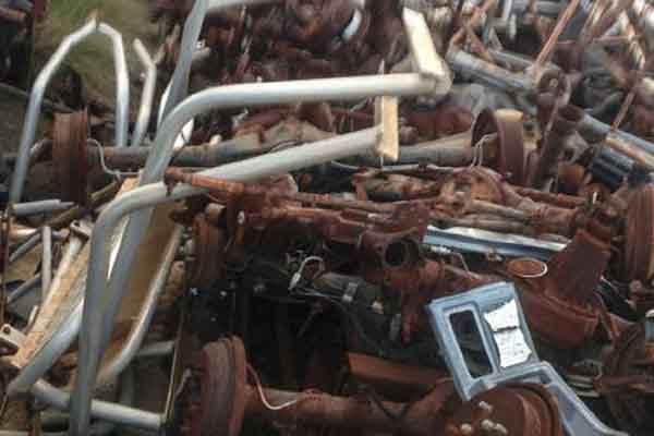
The pile of differentials were looked through, to no avail.
After much deliberation a differential was chosen that would best match. It was from a late 70’s Ford Escort. There was only one year this car came out with seven-inch drum brakes fitted, the rest were all eight inch. The Escort differential was also used in race applications and a great variety of aftermarket parts were available online, like LSD centres. It was also available in a wide range of gear ratio sizes from 3.36:1 to 4.11:1 with increments of approximately 0.2:1 gear ratios between each size.
A differential was purchased secondhand for$400. The price was high as it is a rare part to find being quite old. It was taken to a machining shop to have it shortened 2 inches on each side, the wheel studs drilled to match the wheels on the car and the input flange bolts re drilled and tapped at the proper pitch circle diameter to match the tail shaft. This had to be outsourced, as there was no access to a resplining machine to cut the splines for the shortened axles. The cost came to $750 and was the most expensive part of the car.
Brake line adapters were custom made to convert the different threads, from the cars brake lines, to the differentials brake lines. New mounting points were fabricated and welded to the differential to match the leaf spring spacing on the car. The mounting points were mounted to the differential at a slight angle to tilt the diff downwards, as when the car is lowered on the floor the leaf springs flatten out and change the diff angle. This was taken into consideration.
After painting the car, it was transported to a work college’s house, Warren Bond, who gave me keys to his shed to work on the car and use his tools anytime of the day till the project was finished.
Tailshaft
A tailshaft had to be selected next. Due to then ature of this project, the tailshaft would need to have a flange on both ends of it. As the tailshaft would be mounted with a slight downward angle, it needed to be constructed of two pieces with a centre bearing and sliding coupler in the middle.This would then accommodate changes in length as the differential travels up and down over bumps. A quote on getting a custom made tailshaft built was $1,600. It was undesirable to pay that sort of money on a shaft. Fortunately, by luck, an idea came to check the cars tailshaft I was driving at the time to see if that would fit.
It was a 2004 AWD Nissan X Trail with the motor mounted transversely, like a front wheel drive. It had a tailshaft mounted to the front gearbox that was two piece with a flange on both ends of it. As luck would have it was the exact length to within an inch of what was required for this project. A tailshaft was then found second hand online for $100.
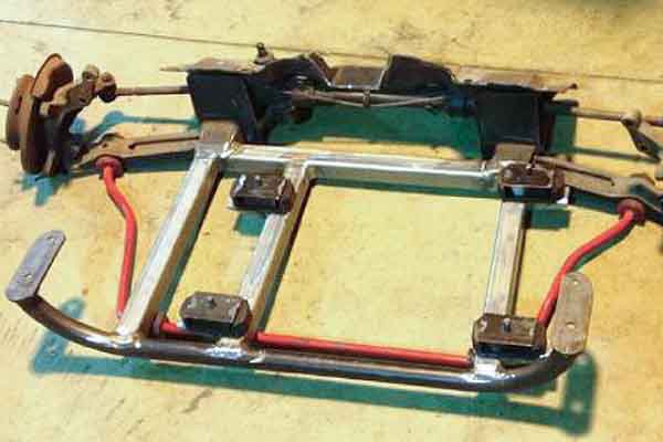
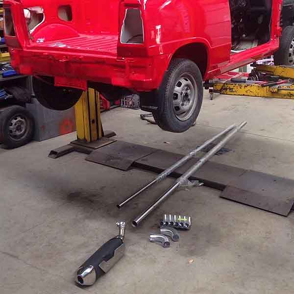
The complete driveline laid out next to the ute.
Tailshaft coupling
This was by far the most critical part on the car to get right. It was calculated that the tailshaft spins at 6,000 RPM when the engine is in top gear revving at 12,000 RPM. The tail shaft sits half an inch away from your foot rotating at this speed and if the coupling fails it would result in severe bodily injuries.
Several factors were taken into consideration when designing this component. Because it is a rotating member it is subjected to cyclic loading forces, which if not designed correctly, will result in cracking from metal fatigue.
This part was created by purchasing a brand new sprocket for $20 instead, and then machining the teeth off of it. This left a blank disc with a hardened spline in the centre. The material properties were then analysed using a spectrometer to determine the composition of the steel. This would help in identifying the correct compatible welding wire to use and weld procedure, for when this would be welded inside a machined flange to couple with the tailshaft.
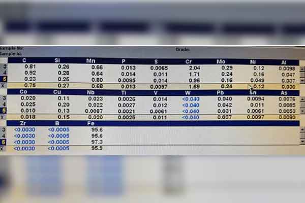
A summary of the metal composition values.
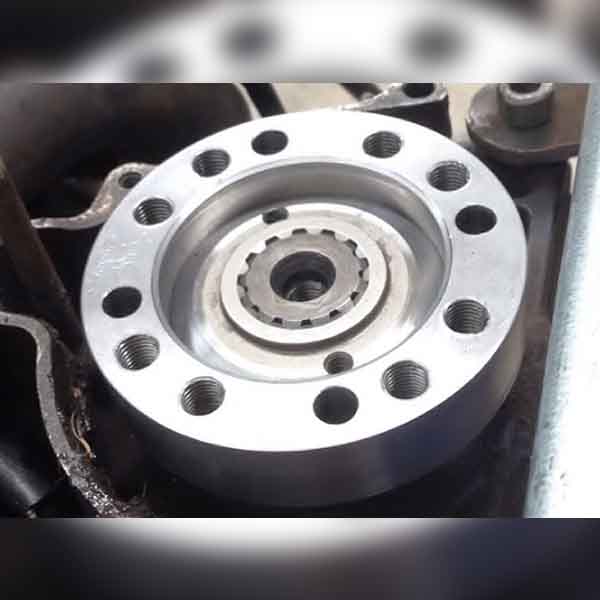
Mild steel was chosen for the material of the machined flange, as it would have good toughness properties from being a relatively soft material. A good friend, Graham Prall, lent his lathe to machine the flange. The four bolt holes for the tailshaft were outsourced to be drilled at the correct pitch circle diameter, but the company failed and had to drill three sets of holes before they got the correct pitch circle diameter, hence why there are 12 holes in this component.
The small spacer ring seen in the picture is to locate the spigot of the tailshaft so it will run true and centred. It was important that the sprocket remained with as large a diameter as possible as to allow the largest amount of weld to hold it to the flange. The spacer ring sits inside the flange after the sprocket has been welded in, to locate the tailshaft while it is being bolted to the flange coupling.
Another problem existed. The sprocket sits loosely on the output shaft, which means it will want to wobble. To overcome this, the flange thickness was such that it was machined to be a press on fit on the output shafts fixed collar behind the spline. This means the primary support for the flange is directly onto the output shaft and not by means of the bolt alone.
This was a critical step to get right, making sure this fit was extremely tight and centre. The flange coupling alone took 30 hours to machine on the lathe to get all the tolerances required for this component to make sure it was correct.
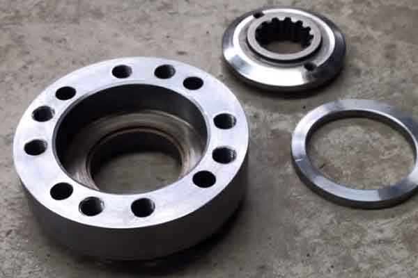
The unassembled tailshaft coupling components.
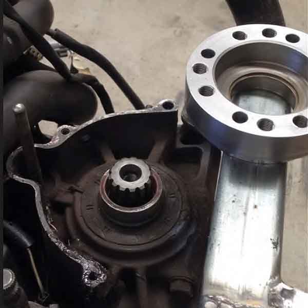
The collar on the output shaft with the machined flange along side of it.
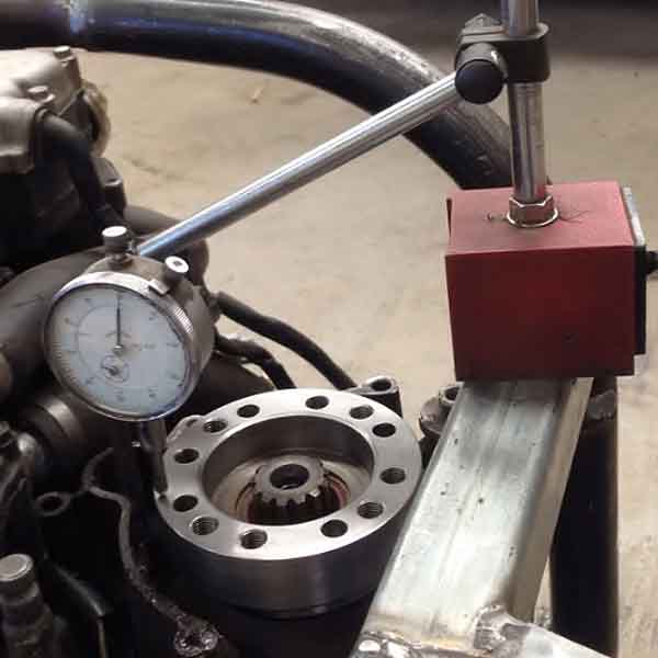
The flange was pressed onto the output shafts collar, and to make sure it was running true, a dial indictor was used to check it was within 0.001” in both planes.
The machined sprocket was placed inside.
Suggestions from a welding engineer recommended using stainless steel welding rod to weld the two dissimilar metals together. Stainless is selected due to its high nickel content and is commonly used in fusing different metals together. Small welds were applied one at a time and the piece was allowed to cool between welds.This would prevent the internal spline from loosing its hardness as the coupling stayed cool during the welding process. It also stopped any excessive heat travelling traveling down the output shaft and melting the rubber oil shaft seal on the engine. The original high tensile bolt was also installed with Loctite to prevent it loosening.
Welds were added slowly until the gaps were filled. The height of the weld was kept as low as possible, so as to allow the spacer ring to sit inside the coupling to locate the tailshaft. A circular hole had to be cut in the chain cover to allow the tailshaft to be mounted to the flange.
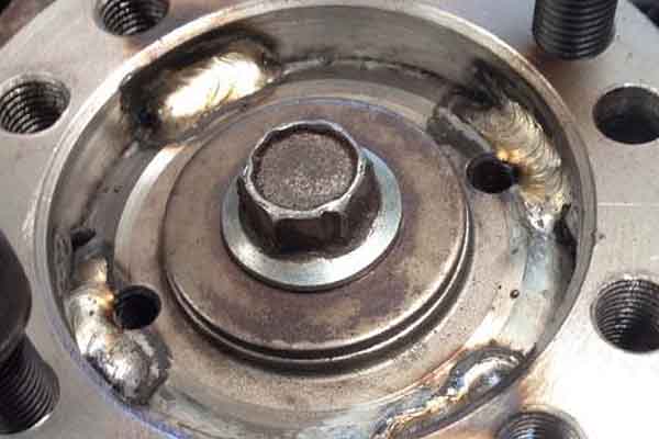
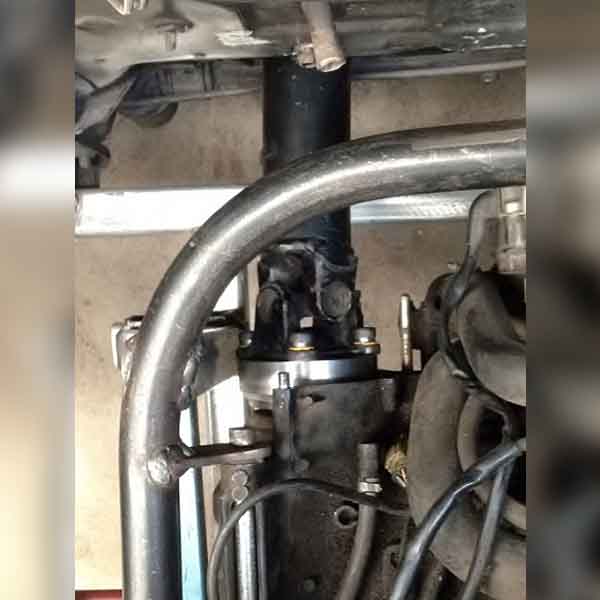
The welded coupling bolted to the motor.
A mockup of the tailshaft bolted to the car without the chain cover.
As the car was front wheel drive it didn’t have a full tunnel running all the way through the vehicle for a tailshaft. Two holes had to be cut in the floor and firewall for the tailshaft to run to the rear of the car.
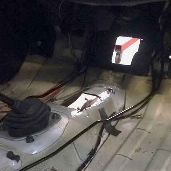
These were the only cuts made to the car, and the offcuts were kept to weld back in when the car was converted back to original. A sheet metal cover was made and bolted to the floor to cover the tailshaft.
Supporting modifications
Once the deceptively complex driveline was resolved, there was still a long list of modifications and fabrication required to mount the motor and get the whole thing running.
Subframe
Originally the cars subframe was going to be utilised and modified to accommodate the motorbike engine, however too much material had to be removed to fit the engine inside the engine compartment and under the hood.
This would prove difficult to make and weld steel around and under the engine to regain the strength of the subframe back, especially with how thin the subframe metal was to weld to. This was a red flag.
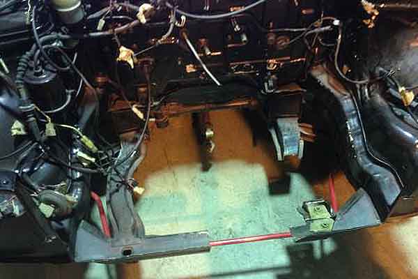
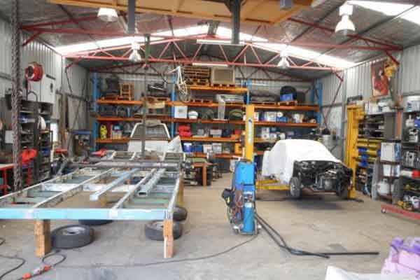
Modifying the original subframe before deciding to move on on to creating a frame from scratch to position the motor in a more suitable location.
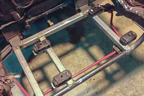
In order for the car to be driven under hard loads all the time the subframe needed to be strong and withstand the extra power delivered. It was decided to fabricate a new subframe that was 2 inches lower and made out of 4mm thick square tubing.
The subframe accommodated the steering rack, lower control arms, sway bar, rubber engine mounts and bolted up to the original holes in the chassis.
Engine frame
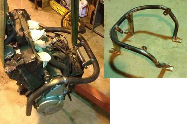
The motorbike engine has many different mounting points to hold the engine that are in awkward inconvenient positions. In order for the motorcycle engine to be isolated from the car to reduce noise and vibration, it needed to be mounted on rubber engine mounts. A frame was fabricated to connect the engine to the rubber engine mounts on the subframe.
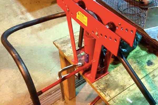
A pipe bender was used to bend the 4mm thick pipe for the engine frame. This was quite the task to try and keep it all one length with multiple bends using the pipe bender.
Some parts had to be finished off in sections, as the pipe bender got in the way of itself when doing two bends right next to each other.
The completed frame test mounted to ensure proper fitment before finalising.
Fuel system and throttle bodies
As the motorbike engine used fuel injection, a high pressure fuel system was required. A surge tank was fabricated for the engine bay that would accomodate the original motorbike fuel pump, which would not fit in the factory fuel tank. A low pressure fuel pump fed the surge tank, and fuel was pumped from there to the injection system at the correct pressure. Return lines ran off both the surge tank and injector rail back to the fuel tank to complete the closed loop circuit.
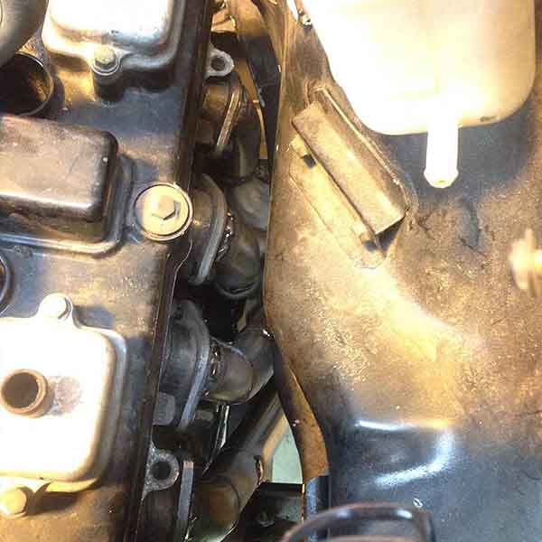
Due to the engine compartment being so small the throttle bodies couldn’t fit directly onto the engine facing upward as there wasn’t enough clearance to shut the hood. As it was not ideal to cut a hole in the hood to fit these in, it was decided to mount the throttle bodies sideways at 90 degrees to the engine and to fabricate 90 degree steel elbows to accommodate this.
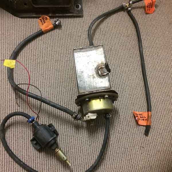
The surge tank with the motorcycle fuel pump fitted to the base of it, and the low pressure fuel pump feeding into the bottom fuel hose.
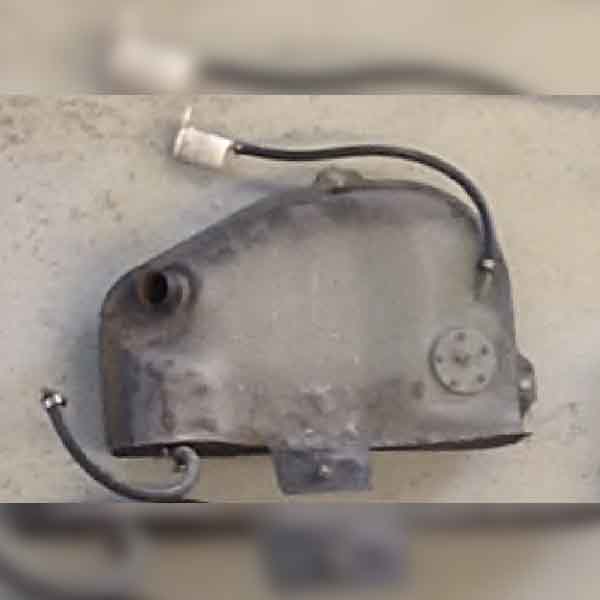
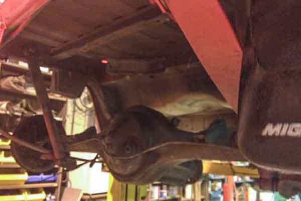
The fuel tank had to be cut in half and a plate welded to the side of it, to create enough space for the tailshaft and differential to fit.
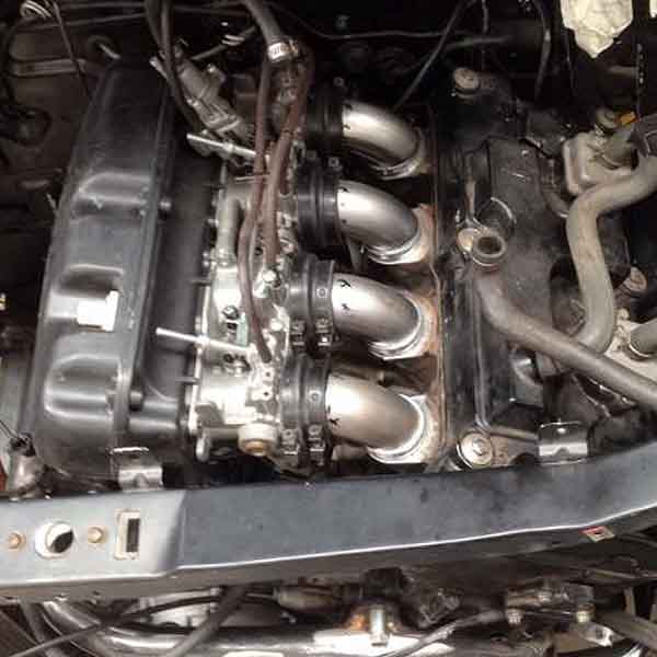
The motorbike throttle bodies were installed with 90 degree elbow adaptors to created enough clearance for the hood to close.
Exhaust system
There was not enough clearance in the engine compartment and ground clearance for the stock headers to fit. Also the lower control arm, sway bar and subframe components were in the way.
The exhaust had to be highly customised with small allowances of clearance to only just fit around everything. This was the only place for the headers to be mounted.
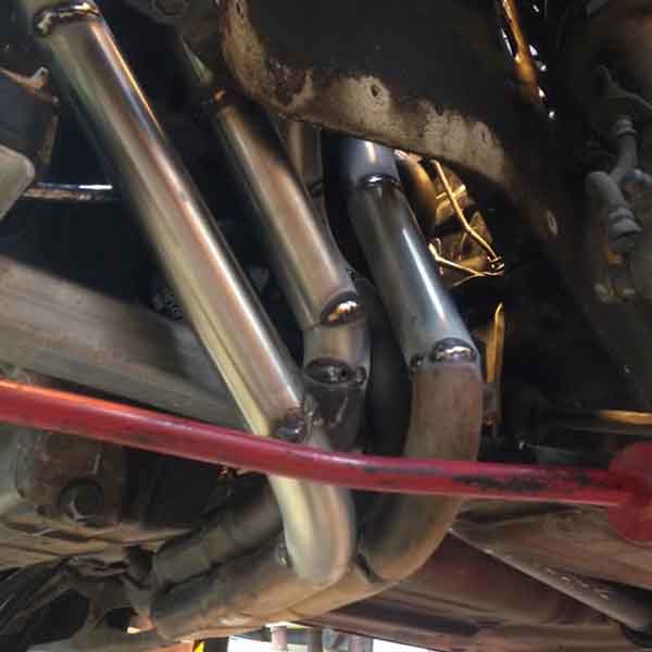
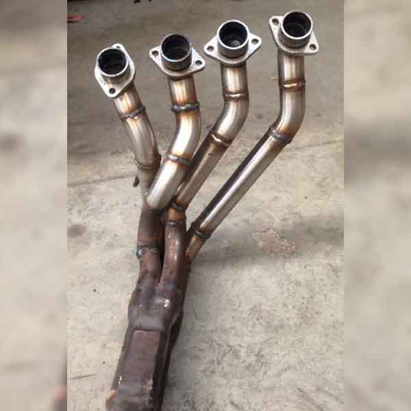
The header pipes were cut off and new stainless steel pipes were fabricated and welded back on to the original exhaust. Below shows the pipes tack welded into place.
How tight the clearance is can really be seen from above.
The rest of the exhaust was made up of stainless steel pipe with a motorbike muffler.
This was all the stainless steel purchased to make the headers and exhaust.
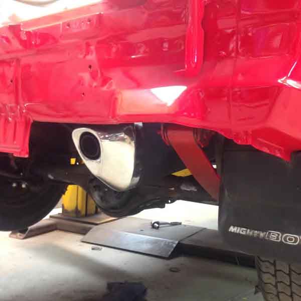
The motorbike muffler was used for aesthetic reasons as well as to leave a clue that this car had a motorbike engine in it.
Cooling system and battery
As this vehicle would be used for racing applications it was essential that the cooling system was designed sufficient enough for the task. The engine oil cooler was fitted to the top front of the vehicle just behind the grill. The oil cooler lines were extended to reach.
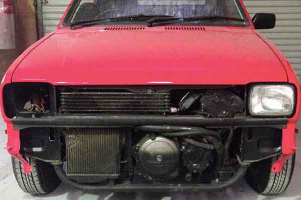
A primary radiator was used from the motorcycle with its cooling fan attached. This was fitted directly to the front of the vehicle with the fan switching on automatically when needed.
A secondary radiator with auxiliary fan was fitted in the spare space on the right side of the engine compartment. This was added to increase the coolant capacity of the system and to also have a manual switched fan for a backup, just encase the primary radiator and fan didn’t provide sufficient cooling in extreme racing scenarios.
The battery had to be shifted over to the other side of the engine bay to fit. A battery box was fabricated out of sheet metal and fixed to the body behind the headlight.
Clutch and gear shifter
The configuration of the factory-fitted clutch cable and gear shifter were not suitable for the motorbike engine, and suitable alternatives had to be found.
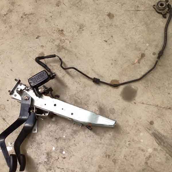
Originally the clutch on the car was cable driven to the gearbox. The motorbike engine had a hydraulic clutch. The pedal box was removed from the car and the hydraulic master cylinder from the motorbike was fitted to the clutch pedal.
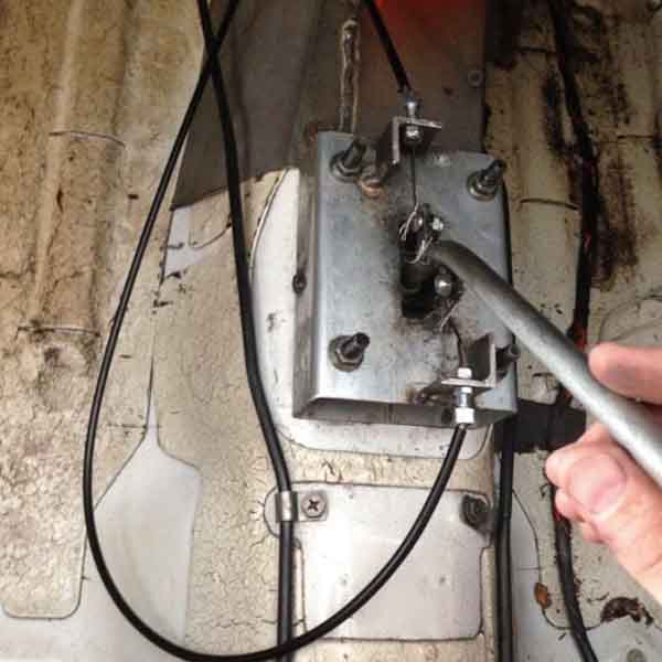
The gear shifter was connected up to the 6 speed sequential motorcycle engine gearbox.
A shifter and housing was fabricated that used two cables to drive the bike's shifter mechanism.
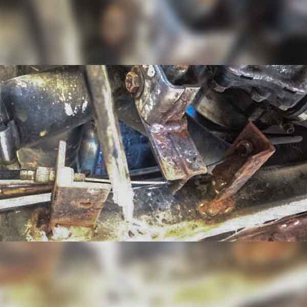
This is the engine end of the shifter cable. The cables pushed/pulled the normally foot-controlled mechanism.
Electrical
Both wiring harnesses from the car and motorbike were used in this project. As the car’s wiring loom was already connected to the basic auxiliary functions of the car, like the headlights, wipers, blinkers, brake lights etc, it was left in place.
The motorbike wiring harness was connected to the battery, engine and ignition switch and was used to run or turn off the engine.
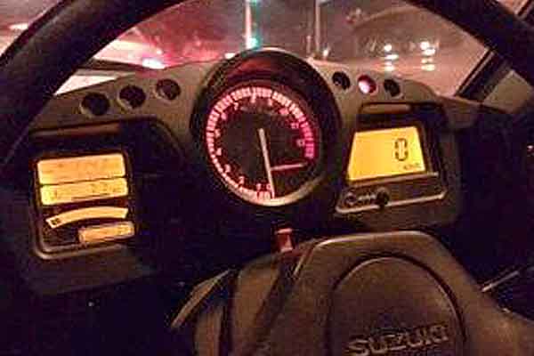
The instrument panel was utilised off the motorcycle as well and was fitted to the dash of the car.
The end result
The project exceeded expectations. Zero to 60mph time was 3.5 seconds. This is only 1.5 seconds slower than the motorcycles zero to 60 time. The car was capable of spinning the tyres all the way up to top gear.
With the exception of two holes cut in unobtrusive areas of the body, the entire conversion was completely bolt-in and reversible.
Eventually the ute was returned to original factory configuration and sold, and the removed motorbike conversion kit sold to another MightyBoy owner.
The engine bay of the completed conversion.
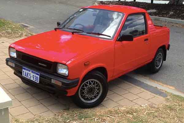
The ute as completed.
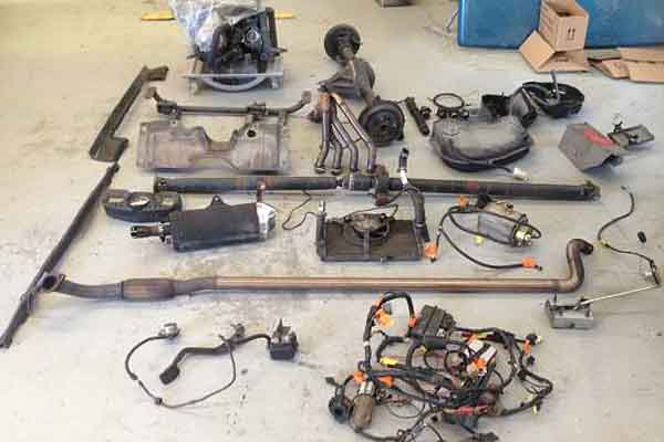
All of the parts that made up the conversion.